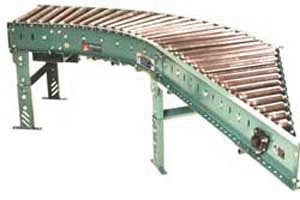
| 138LRCS | |
| Light Duty Belt Driven Live Roller Curve Spur | |
 |
|
| Download Hi-Res Tech Drawings (pdf format) | |
| Download catalog page in pdf format | |
| 138LRCS | |
| Light Duty Belt Driven Live Roller Curve Spur | |
 |
|
| Download Hi-Res Tech Drawings (pdf format) | |
| Download catalog page in pdf format | |
| SPECIFICATIONS |
|
TREAD ROLLERS:
1.9" dia. to 1-3/8" dia. x 16 ga. tapered rollers, model 138T; 1-3/8" dia.
x 18 ga., model 138G w/ 5/16" hex, galvanized straight tangent rollers. ROLLER CENTERS: 1-9/16" measured at inside radius of unit. PRESSURE SHEAVES: Provides drive belt pressure to upper tread rollers. BELT: "B" section V-belt. TAKE-UP: Screw type adjustable sheave with flat idler sheaves provided to maintain belt tension. TANGENTS: 12" opposite spur end on 60°/30° unit; 18" opposite spur end on 45°/45° unit. SPEED: 60 FPM, constant. BEARINGS: End shafts are supported by precision, heavy duty, lubricated, ball bearing units with cast iron housings. BED:
6" x 1-1/2" x 12 ga. formed steel channel frame. |
| 3 WEEK SHIPMENT |
NOTE: This unit is not recommended for accumulating loads. |