|
TREAD ROLLERS:
2-1/2" dia. to 1-11/16" dia. x 14 ga. tapered rollers (model 254T); 1.9"
dia. x 16 ga. (model 196S) straight tangent rollers.
PRESSURE
SHEAVES: Provides
drive belt pressure to upper tread rollers.
BELT:
"B" section V-belt.
TAKE-UP:
Screw type adjustable sheave with flat idler sheaves provided to maintain
belt tension.
TANGENTS:
12" opposite spur end on 60/30 unit; 18" opposite spur end on 45/45 unit.
BED:
7" x 1-1/2" x 12 ga. formed steel channel frame.
BEARINGS:
End shafts are supported by precision, heavy duty, lubricated, ball
bearing units with cast iron housings.
FLOOR
SUPPORTS: SM-6
adjustable 31-1/2"-43-1/2" TOR. Supports should be lagged to floor
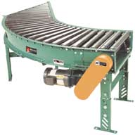
MOTOR DRIVE:
1/3 HP, 230/460/3, 60 cycle, ODP right angle gear motor, located at infeed
end of curve below bed.
SPUR
HAND/DRIVE LOCATION:
Drive located on outside of curve. Specify hand of spur as "left hand" or
"right hand" and location of drive specified as "left hand drive" or
"right hand drive". NOTE: Drive location determined with reference point
located at outside of curve. For models slave driven (less drive), specify
drive shaft location.
BELT SPEED:
60 FPM, constant.
ROLLER CHAIN:
Drive shaft is driven by No. 50 chain.
CAPACITY:
500 lb. total distributed live load.
ELECTRICAL
CONTROLS: Optional |